Projection Mapping
This is a small compilation of (projection) mapping techniques. It was only during the last 20 years when projectors became affordable and powerful enough – the same applies to computers – to enormously influence the way we work and thus the way art is being produced. Public projections evolved from technically enhanced street art and from music driven VJing (party visuals) to an art of its own.
Additionally: mapping virtual to real content probably becomes increasingly important.
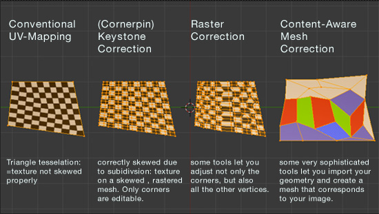
The following compilation is about skewing an image of a projector so that its content fits the object being projected on.

Software References:
Keystone Correction: http://keystonep5.sourceforge.net/, http://vdmx.memo.tv/msa_quad_warp*,
Blender Example File*, MadMapper
Mesh Correction: http://meshwarpserver.org/
* implemented with GLSL shader, you may want to know more about bilinear interpolation, 2
Spacial Illusions
 Images being mapped to a facade have a long tradition. Especially in combination with spacial illusions Renaissance artists tried to apply their newly acquired knowledge about optics. After the Book of Optics was available as an italian translation around 1400 many frescos where created, which tried to evoke the illusion that a room would have a virtual extension to another room – or heaven, in case the fresco was applied to the ceiling.
Of course spacial illusion have been well elaborated among facade projections as well. With the means of computers and projectors we are able to animate our illusions or make them even interactive. One major restriction though remained: you need to assume a viewing angle at which the viewer looks at your projection. Spacial illusions work only for the exact angle that was assumed when the illusion was created.
In case of animation or interactive installations such illusions usually are created with 3D animation software and the assumed viewing position corresponds to the position of the virtual camera inside such a software 3D environment.
The mapping techniques shown above won’t allow any movement of the assumed viewing angle, because the picture taken from the virtual camera needs to be distored for every camera position manually.
Move the view point with the Shifted Camera Method
This can be solved with another sophisticated mapping technique: the shifted camera method. It allows to take pictures from different viewing angles but having the image already distorted by photographical means (which are modeled in virtual cameras too) before it is rendered to a file. Even more useful: the distortion of the image (camera shift) can be calculated depending on the position of the camera.
![]()
with offset being the distance between the center of your facade and the position of your camera in parallel direction to the facade. Using the Blender’s “Driver” feature the camera’s shift is being automated by applying this formula (Blender file at the bottom).
Please note that the shifted camera method has to be combined with a correction method explained at the top. It is “only” able to produce intermediate imagery that needs to be mapped with e.g. a cornerpin keystone correction in order to map it exactly. The intermediate imagery can be considered as “normalized” though, which means that no matter what view angle you choose the image is being distorted to the same dimensions (if you use the formula to calculate the shift parameters). In other words: The intermediate images look as if they would stick perpendicularly to a facade, while the viewing angle may differ (video below). The downside of this method: it works only for flat facades. You can’t do projections on two perpendicular faces (=over the edge).
Blender-File: shifted_camera_move.blend ![]() Lukas Treyer
Lukas Treyer
Focal width (zoom)

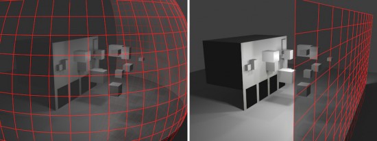
When rendering spatial illusions the focal width should remain at 50mm. As illustrated in the image, an image with too much wide angle doesn’t create the same effect as an image with approximately the same focal width / zoom as our eyes have. This is because your projected illusion should seamlessly integrate with the context, e.g. the rest of the building, which means “outer” perspective lines, outside your projection. Because your eyes perceive the context at around 50mm, your projection should match the perspective lines, and therefore should be rendered at 50mm.
Consequently this forces you to capture your illusion with a fixed distance, since the focal width is fixed at 50mm. This also means that the position of the spectator and camera are not completely congruent but only their viewing angle towards the facade. Another consequence is, that the camera has to follow a sphere in order provide illusions from different angles. Related to the camera shift method this means the camera should move only along a plane parallel to the facade.


